Water Well Wiring Diagram
The submersible pump circuit diagram is a visual representation of the electrical components that make up a submersible pump system. At its core, a submersible pump is made up of a motor, impeller, and a series of electrical wires and connections.
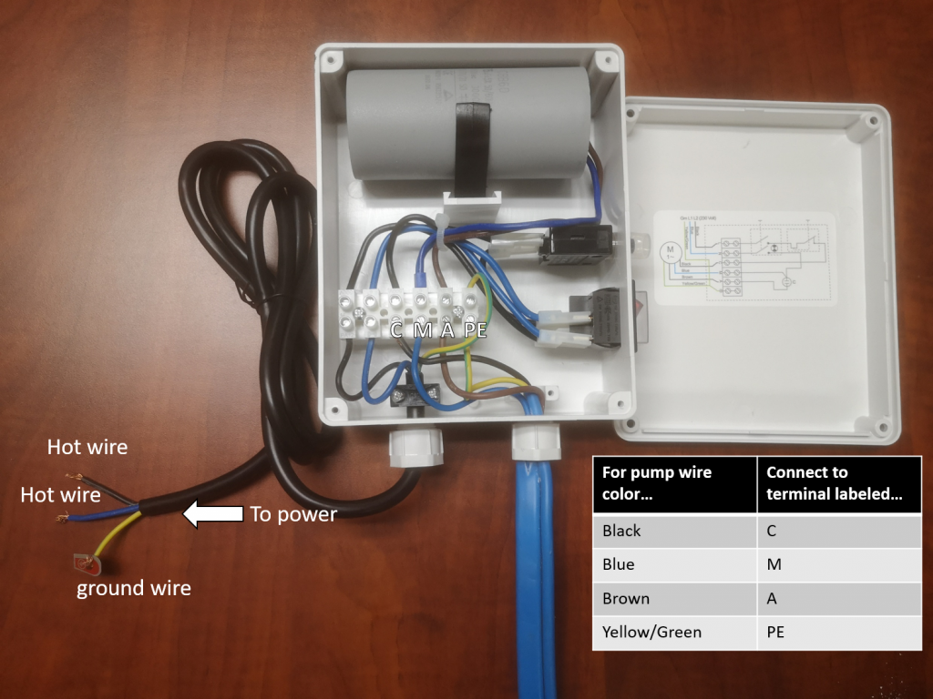
How to Wire Your Hallmark Industries Deep Well Submersible Pump The Pump Doc
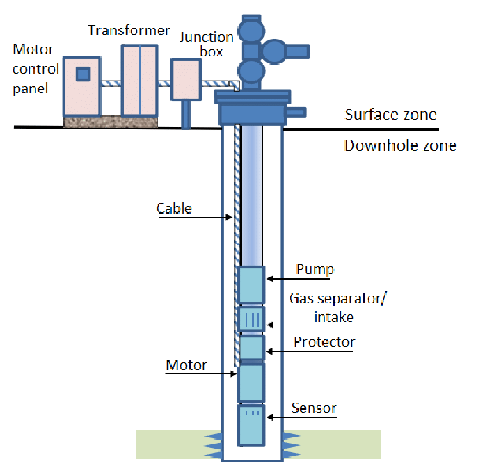
The submersible pump system consists of both downhole and surface components. The main surface components are transformers, motor controllers, junction box and wellhead. The main downhole components are the motor, seal, pump and cable. Additional downhole components may be included to the system: data acquisition instrumentation, motor lead.

LIDER [2 HP][Single Phase Submersible Pump Starter][LBMSP 2036] indiacitymart
A submersible pump also called an electric submersible pump. it is a pump that can be fully submerged in water. the motor is hermetically sealed and closed c.
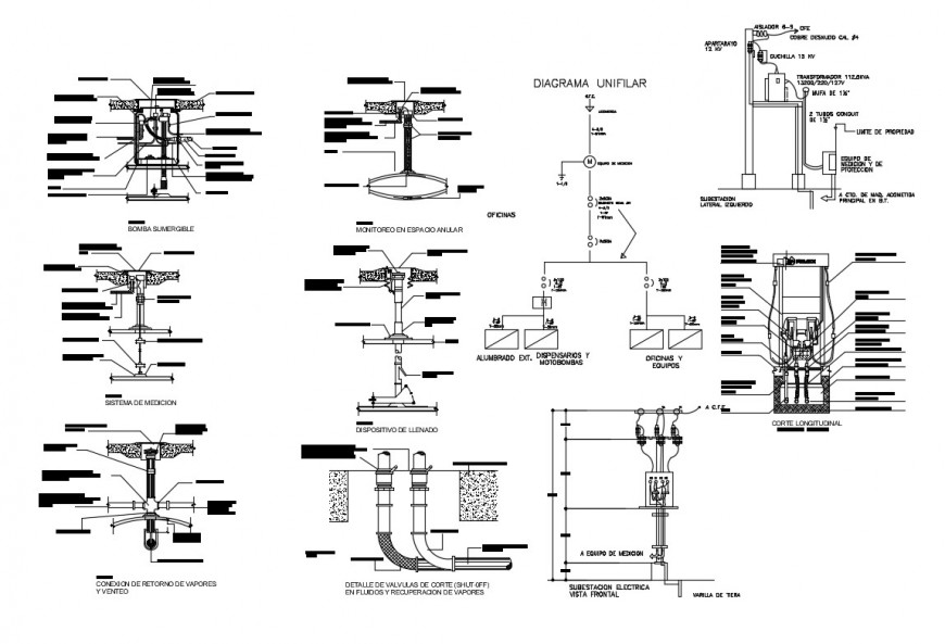
Submersible pump connection and installation details dwg file Cadbull
• Insure that main power is disconnected, turned OFF, before wiring any compo - nents. • Wiring should be performed only by qualified technicians. • Wiring and Grounding must be in compliance with national and local codes. • Restrict the flow with a ball or globe valve, 1/3 open, before starting pump for first time.

3 phase submersible pump starter wiring diagram
This video is explained about single phase submersible pump / motor control box wiring connection diagram. If you have any questions, please comment below th.
Submersiblepumpdiagram Aarohi Embedded Systems Pvt. Ltd.
Today I will share with the complete diagram of submersible pump. In submersible motor we use wire connectors, DPST switch (double pole single throw) , capacitor and reset able thermal overload protector. From the switch we can switch on or off the motor , and reset able thermal overload protect our motor during high current flow.

Wiring A Submersible Pump
Learn about Submersible starter connection, submersible pump panel full wiring diagram and connection with contactor. Submersible pump starter Capacitor conn.

Wiring Diagram Of Control Panel Box Of Submersible Water Pump
Overall, a Flygt submersible pump wiring diagram serves as a valuable resource for understanding the electrical configuration and connections of the pump system. It helps ensure proper installation, operation, and maintenance, leading to optimal performance and longevity of the pump. Whether you're an electrician, technician, or operator, a.

Submersible Pump Wiring Diagram
A. WIRING DIAGRAMS A. WIRING DIAGRAMS 20 21 Typical Wiring A Diagrams 3 1 2 5 36 97 1 L1 T1 T2 T3 L2 L2 3 To Pump Motor Ground Level Control Ground Pressure Switch Lower Upper Electrode Input Power (As Required By Level Control) To Fused Disconnect Or Circuit Breaker 3Ø Furnas Magnetic Starter Line Load Line Load 3 Phase Starter Magnetic.

110 Volt Well Pump Wiring Diagram
Today I am here to share with you the 3 phase submersible pump wiring diagram. In which I control a three-phase submersible pump motor using a magnetic contactor. Not only a contactor but also install the thermal overload relay which will protect the motor from burning in case of overcurrent flow to the circuit.
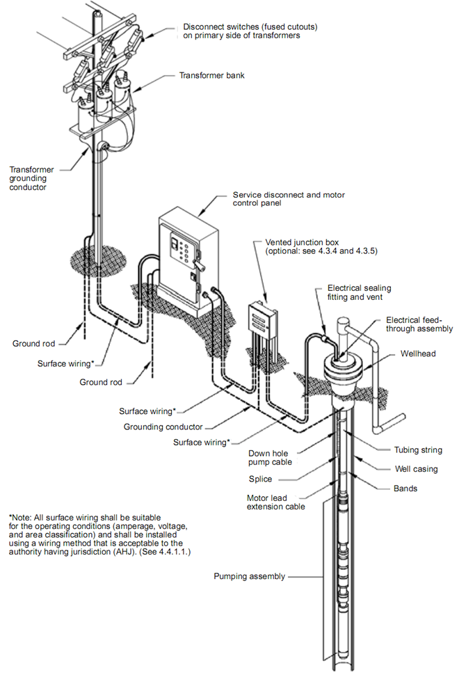
Submersible Pump System Overview main surface and downhole components
Step-1: Gather All Necessary Equipment and Material Through the whole process, the single-phase 3-wire submersible pump wiring diagram will help you a lot to stick in the right path. Along with the wiring diagram, we need to use some essential elements, and they are: A capacitor A resistible thermal overload and

How to Control a Lamp / Light Bulb from Two places Using Two Way switches For Staircase Lighting
1. Check the bore - looking for damage to the bore casing, check the depth and the standing water level. 2. Check the kit of supplied components. Check the details of the drive motor - looking for power supply rating, identify weather it is a 2-wire single phase, a 3 wire single phase and needs a pump stater box or 3 phase configuration.
surmersible for well pump wiring diagrams
A standard submersible pump wiring diagram provides step-by-step directions for connecting the necessary wires and switches. The diagram starts with the power source, which is typically a breaker box or fuse panel.

Should Munching meteor water pump control box wiring diagram easy to be hurt mound terrace
The above 3 wire submersible pump wiring diagram / or single phase submersible pump wiring connection with starter diagram is too simple. However for better understanding kindly watch the below video tutorial which is in Urdu & Hindi language. Single Phase Submersible Pump Starter Circuit Diagram || Hindi & Urdu Watch on
INSTALL A SUBMERSIBLE PUMP 6 Lessons for doing it right
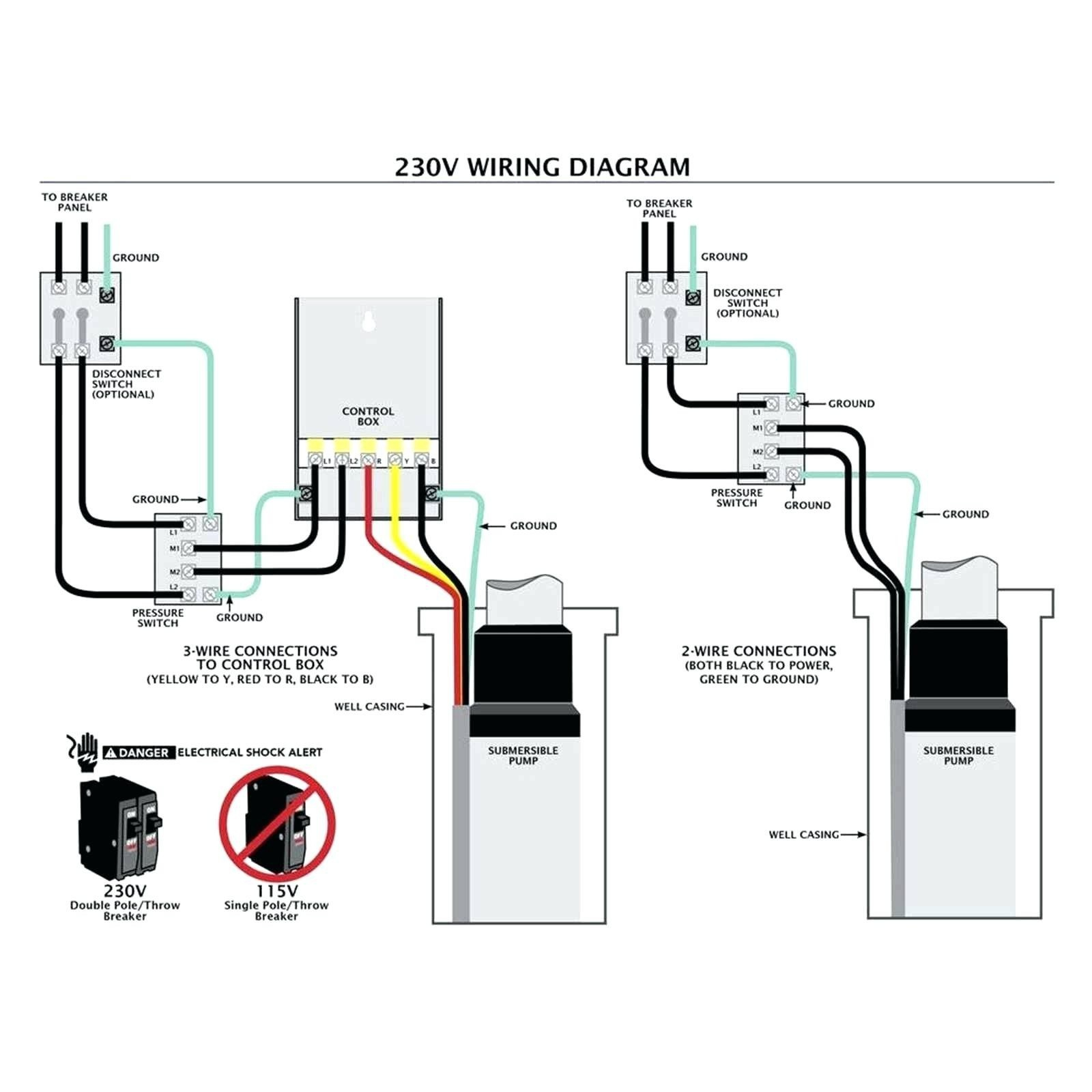
Deep submersible well pumps will be either 2-wire or 3-wire well pumps, and 3-wire well pumps will need a separately installed control box. Two-Wire Well Pump Wiring Diagrams 2-wire well pump diagrams are slightly easier to understand, and are more straight-forward to wire.
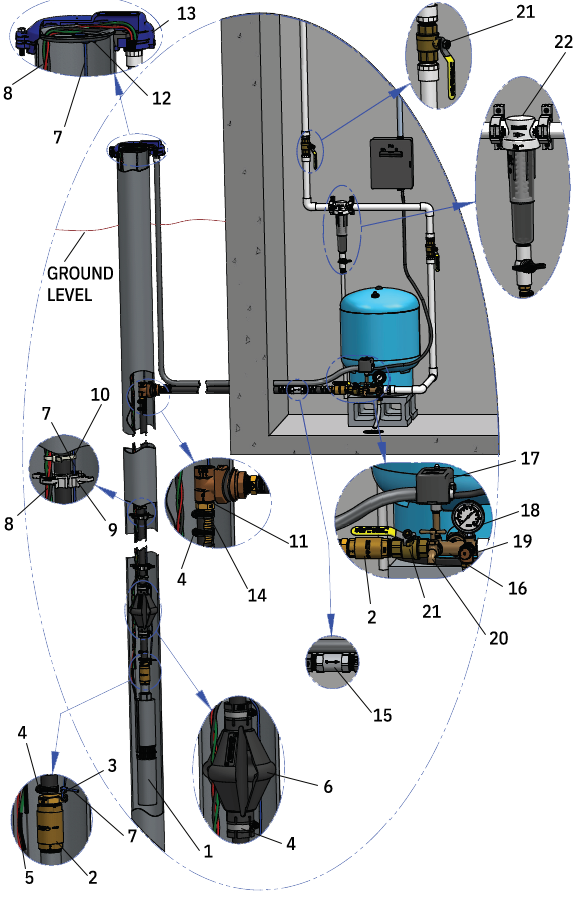
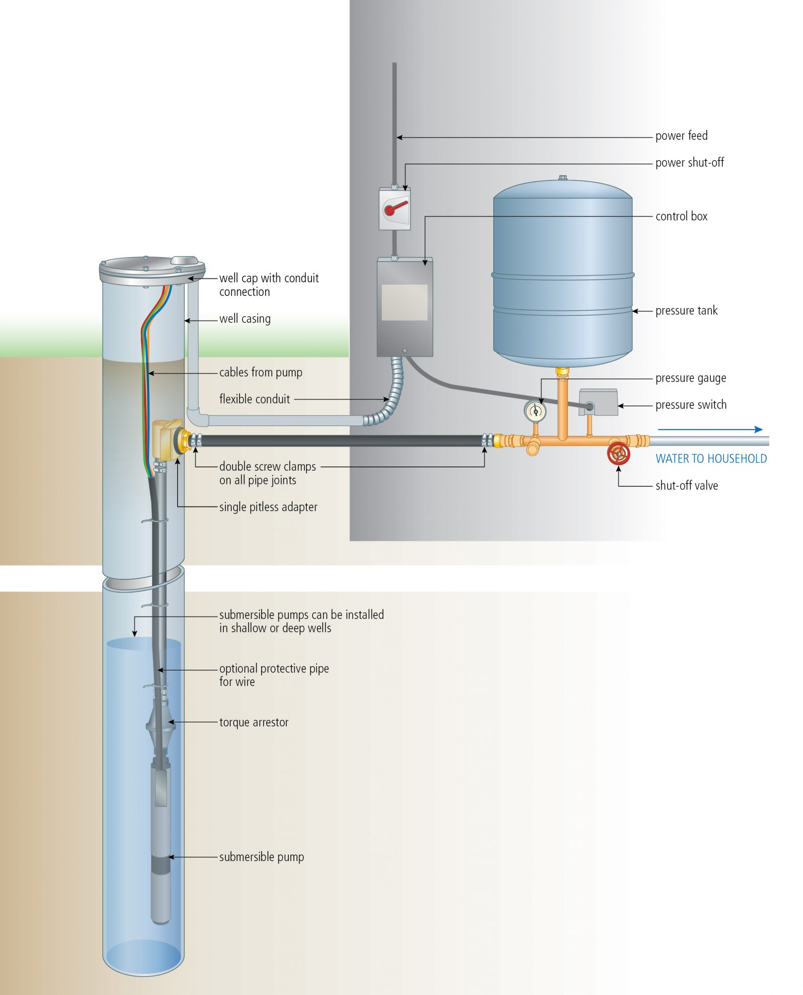
Components of a Typical Submersible Pump Installation
A submersible pump wiring diagram is a visual representation of the components and cables used to connect the pump to its power source. It provides detailed information about the connections made between the various components, as well as the voltage and amperage requirements for each connection.